Goal: Create a simulated root cellar using a used freezer and a Raspberry Pi microcomputer to store garden crops using correct temperature and humidity while avoiding dangerous electrical wiring.
Background: I do not have a basement or a insulated place to store harvested crops from my garden. I do have an unheated shed which gets very hot in summer and cold in winter. I could dig a hole in the ground but I thought it best to try using simple inexpensive tech to solve the problem. The beauty of my approach is that if I can it setup correctly once, I can clone my sd card, pick up another used freezer, and adjust script code to change target temperature for other crop conditions.
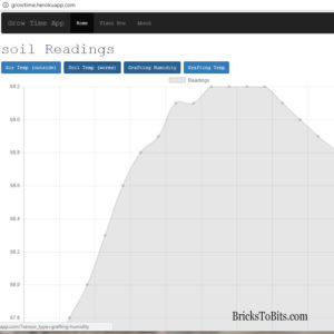
I expect I probably will not get the humidity and air exchange part right but I will start with controlling temp and as the season changes I will have a web page to show me a chart of high and low temps as well as humidity to see how well I am doing. Then I can make adjustments to control things better.
Expanding on the grafting chamber idea I have a theory that I can make a simulated root cellar with a freezer and a Rasperry Pi.
I should be able to use a controllable power relay to turn the freezer on and off with great accuracy based on the measured temperature inside. The first iteration of this project will read the temperature inside the freezer, turn the freezer on or off based on the temperature reading, and also read the internal humidity for monitoring purposes.
Initially, I will use a spray bottle and a quick door close for the humidity control and air exchange. Later, I can add some sort of humidifier if necessary to control humidity more accurately depending on how well it is maintained.
I will be using a Raspberry Pi v3. I will also need the following:
You might also want a network cable, usb keyboard, and hdmi cable to connect to the Pi initially for setting up wifi and SSH remote access (shut off be default now).
We are going to use the Python programming language to read a combined temperature and humidity sensor, control the freezer’s power plug based on internal temperature reading, then save the resulting sensor readings to a cloud database for later reporting.
Example of web site graph of temperature and humidity I generate for my worm bin
This tutorial does not cover setting up a database or creating the web site to show the charts. Incidentally, I use Heroku for hosting my db and my Rails 5 web app. You can use any postgres db host and whatever web tech you want for reports. You could even send notifications or save to text file for periodic review
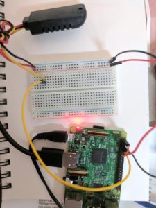
The sensor we are using is the DHT22 AM2302. Lucky for us Adafruit has a library to access it.
I am attaching the gpio 4 pin to the yellow (data) wire on the sensor. I attached red to red and black to black on the breadboard. From the breadboard I run red to a power pin and black to ground.
connecting the temp/humidty sensor to a breadboard for initial testing.
Now you can test the connections and make sure it all is hooked up correctly
The full python code to read sensor and write to database. This is a separate script from controlling the power supply because I want the writing to database occurs once per hour, while the power relay script runs every few minutes as needed to keep the freezer in the right range for your needs.
Monitor and Save Script
nano check-sensors.py
import os, sys, Adafruit_DHT, time
from datetime import datetime, date
import psycopg2
import RPi.GPIO as GPIO
#air temp sensor setup
sensor = Adafruit_DHT.AM2302 #DHT11/DHT22/AM2302
pin = 4

#sensor_name = "grafting"
# AIR TEMP/HUMIDTY functions
def save_to_db(temperature,humidity):
 try:
 connect_str = "dbname='mydb' user='myuser' host='somewhere.amazonaws.com' password='somereallylongpasswordtoremember'"
 # use our connection values to establish a connection
 conn = psycopg2.connect(connect_str)
 # create a psycopg2 cursor that can execute queries
 cursor = conn.cursor()
 datime=datetime.now()
 # my values from sensors are stored in reading and sensor_type is for me to make up my own custom labels for whatever sensor I may want to add in the future
 cursor.execute("INSERT INTO readings (value, updated_at, created_at, sensor_type) VALUES (%s, %s, %s, %s)",(humidity,datime,datime, 'rootcellar-humidity'))
 cursor.execute("INSERT INTO readings (value, updated_at, created_at, sensor_type) VALUES (%s, %s, %s, %s)",(temperature,datime,datime,'rootcellar-temperature'))
 conn.commit()
 cursor.close()
 conn.close()
 except Exception as e:
 print('problem saving')
for x in range(2):
 Adafruit_DHT.read_retry(sensor, pin)
try:
 hum, temp = Adafruit_DHT.read_retry(sensor, pin)
 if hum is not None and temp is not None:
 ftemp = (temp *9.0) / 5.0 + 32.0
 save_to_db(ftemp, hum)
except (KeyboardInterrupt, SystemExit):
 print('failed')
hint: CTL-O to write and CRL-X to exit nano editor.
Control the Temperature
The Hardware
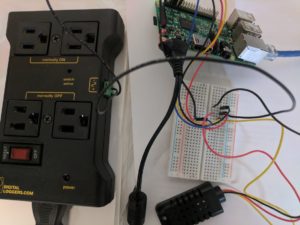
We need to wire the power relay to the Pi. I picked up a roll of solid core 22 gauge wire to make the length I need. I don’t know what the physical limit of the wire length is. Mine will probably be a couple of feet in length. I make two of these. One for connecting to pin 18 and one for ground. Attach them to the breadboard.
Note: This tripped me up at first. The power relay I purchased has a pair of plugs for ‘always on’ and another pair for ‘always off.’ My script uses always off.
I apologize in advance for the photo. It probably would make more sense as a diagram but I wanted you to get a basic visual of what is happening so far.
the overview of the connected Raspberry Pi and power relay
power-relay.py
import os, sys, Adafruit_DHT, time
from datetime import datetime, date
import psycopg2
import RPi.GPIO as GPIO
import time
#air temp sensor setup
sensor = Adafruit_DHT.AM2302 #DHT11/DHT22/AM2302
pin = 4

GPIO.setmode(GPIO.BCM)
relay = 18
GPIO.setup(relay, GPIO.OUT)

for x in range(2):
 Adafruit_DHT.read_retry(sensor, pin)
go = 1
while go:
 try:
  hum, temp = Adafruit_DHT.read_retry(sensor, pin)
  if hum is not None and temp is not None:
   ftemp = (temp *9.0) / 5.0 + 32.0

   if ftemp > 50:
    GPIO.output(relay, GPIO.HIGH)
    print 'freezer on'
    print 'temp is ' + str(ftemp)
    time.sleep(180)
   else:
    GPIO.output(relay, GPIO.LOW)
    print 'freezer off'

 except (KeyboardInterrupt, SystemExit):
  go = 0
  print('failed')
Automate Running of the Scripts
The check-sensor.py should run every hour. For this we will use crontab.
to edit cron
crontab -e
when prompted for a text editor to use I chose nano
To set your check-sensor script to run on each hour add this line:
The power-relay.py shoud run at startup in the background and run continuously. The script itself handles the requency of in this case.
To start a script running at startup you could edit the following:
sudo nano /etc/rc.local
which I have done in the past, but the correct way to to create a service. If your script stops working using the rc.local method it may not restart when system reboots.
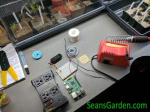
That should be enough to get you started. I am going to solder the wires to a printed circuit board so they do not fall out of the breadboard every time I move it.
I will play around wih this now to fine tune my food storage system. I have the flexibility to add additional devices like heat mats when its cold, humidifiers, or fans for air exchange if necessary. I can also create completely separate systems for fruits or vegetables that require different humidity or temperature ranges.
My all-blue heirloom potatoes are nearing harvest so I better go put this into action. Drop me a line with questions or comments.
PS- I am just starting to harvest my late potatoes now (early July). My first few storage trials with a handful of carrots and a spray bottle was not enough to keep humidity high enough to keep them crispy. I added a wet burlap bag on a shelf which helped hold the humidty around 60-65% with a spray bottle. It was still not quite enough. Next I will be adding potatoes in damp burlap bag and maybe some in a plastic box with a lid and air holes to keep the humidty just right.
My main growing interest is heirloom tomatoes, but I like to grow many other things too. Unique in some way such as flavor or color is always preferred.
I focus on soil health, using regenerative agricultural methods to develop a diverse and healthy soil biome to avoid chemicals and soil tillage.
 That should be enough to get you started. I am going to solder the wires to a printed circuit board so they do not fall out of the breadboard every time I move it.